| Basic Methods | |
|---|---|
| Arc | Draw an arc of an ellipse |
| Blank | Clear the entire drawing area |
| Box | Draw a box (filled and line only) |
| Chord | Draw a chord (a closed arc) |
| Ellipse | Draw an Ellipse |
| Line | Draw a Line |
| Polygon | Draw a Polygon |
| Show | Write text to the drawing area |
| Draw Class Methods | |
|---|---|
| Arc | Draws an arc |
| Barcode | Draws a PDF417 compatible 2D barcode. |
| BestFit | Calculates the best proportional scaling when passed dimensions. |
| Blank | Clears the drawing area |
| Blur | Blurs a layer, supports blurring horizontally, vertically, or a standard blur. |
| Box | Draws a rectangle |
| Captcha | Creates a CAPTCHA from a passed string. This is used to create an image that a human can read, but is difficult for a machine to read, for web based forms etc. |
| Chord | Draws a chord (and arc with the ends connected by a straight line) |
| ClarionToRGB | Converts a Clarion color to a standard RGB color . |
| ColorRange | Used to calculate the colors at two points anywhere on a color gradient |
| Create256 | Create a 256 colour bitmap from the 24 bit version. |
| Curve | Draws a smooth curve through the points passed. |
| Cylinder | Draws a variety of cylinders, with multiple shading options |
| Display | Displays the draw control. Display() needs to be called every time control needs to be updated |
| Ellipse | Draws an ellipse |
| EnumFontFamilies | Populates a queue for all available fonts on the system. |
| ErrorTrap | The default error handler, allows error messages to be turned on or off, as well as providing the ability to easily customise the error handling throughout Draw. |
| FileToString | Reads the content of a file into a string, also see StringToFile |
| FindPixel | Travel across the drawing in a specific direction until a pixel of interest is located. |
| Flood | Floodfill an area of the drawing. |
| FormatMessage | Returns the error message for a passed Window API error code. |
| Fullscreen | Uses the built in functions to get the metrics for the current monitor and resizes the window to the full size of the screen (see the Fullscreen example). |
| GetDeviceCaps | Gets information about the current device capabilities (screen size, resolution etc.) |
| GetDevicePixel | Returns the color of a pixel anywhere on the screen |
| GetDisplay | Loads the current image control contents into the Draw buffer, useful for getting an image that Clarion has loaded into the control. |
| GetIconHandle | Gets a handle to an icon on disk or in a resource for passing to LoadIcon |
| GetImagePixel | Returns a pixel on the Draw control, faster than GetDevicePixel, and the coordinates are relative to the origin of the Draw control. |
| GetPixel | Identical to GetImagePixel, simply provides an alternative name. |
| GetMonitorInfo | Retrieve information about the monitor based on the passed handle (including the monitor size and workspace size). |
| GetWindowsColors | Populates the Draw Windows colors variable with the current interface colors stored by Windows. |
| GrabScreen | Grabs the specified area of the screen and loads it into the Draw control |
| Grayscale | Converts an image to grayscale. |
| HalfEllipse | Draws half of an ellipse |
| Highlight | Turns a highlight on and off over the area specified. Gives a "selected" effect. |
| HsvToRgb | Converts an HSV color to a standard Clarion RGB color |
| Image | Displays and image from a file |
| ImageDimensions | Returns the pixel dimensions of a bitmap image file. |
| imageFromBuffer | Writes from a buffer that contains RGB data to a layer as an image. |
| Init | Initializes the Draw control, called automatically |
| Init256 | Initializes 256 colour drawing capabilities |
| Kill | Destroys the Draw control, called automatically |
| Kill256 | Halts 256 colour drawing and cleans up |
| LengthenLine | Calculates the coordinates of a lengthened |
| Line | Draws a line |
| ListDisplayDevices | Lists all display devices on the system and populates a queue with the details |
| ListMonitors | Retrieves information about all of the monitors on the system and fill a queue with the details include the monitor handle, the coordinates and the workarea. |
| LoadIcon | Places an image from an icon file onto the Draw control |
| Log | Log to the OS debug output (see Debugging and Logging) |
| MetallicCylinder | Draws a double shaded cylinder with a metallic look |
| MonitorFromRect | Returns a handle to the monitor that the passed Rect is on |
| MouseX | Return the current x position of the mouse relative to the Draw control |
| MouseY | Return the current y position of the mouse relative to the Draw control |
| PieSlice | Draws a shaded slice of a pie (a segment of a pie chart). |
| PointInPolygon | Returns whether an x and y coordinate are within a polygon. |
| PointInPieSlice | Whether a coordinate is within a specific pie slice (ellipse segment) |
| Polygon | Draw a polygon |
| Putpixel | Puts a pixel on the Draw control |
| RadLine | Draws a line radially (from a point to a length along an angle) |
| ResetDisplayArea | Resets the Display to redraw the entire canvas (see SetDisplayArea) |
| Resize | Changes the size of the Draw buffer |
| ResizeControl | Changes the size of the Clarion control Draw uses |
| RgbToHsv | Convert and RGB color to an HSV color |
| RoundRect | Draw an round cornered rectangle. |
| SetDisplayArea | Limits the display command to a rectangular area, can dramatically increase display performance. |
| SetFontColor | Sets the current Draw font color |
| SetFill | Sets the current fill type to patterned instead of solid |
| SetPenColor | Sets the current Draw pen color |
| SetPenstyle | Sets the current Draw pen style |
| ShadeBox | Draws a rectangular box with multiple shading options |
| ShadeEllipse | Draw an ellipse shaded from one color to another. |
| ShadeLine | Draws a line shaded from one color to another |
| ShadePolygon | Draw a polygon horizontally shaded from one color to another. |
| StrHeight | Returns the height of the current font |
| StrLen | Returns the length of a string in pixels |
| Sphere | Draws a sphere shaded between two colors (the "sphere" can be elliptical). |
| SetPenWidth | Sets the current Draw pen width |
| SetFill | Sets the current fill style, allows patterned fill to be used |
| SetFont | Sets the current font attributes to use. |
| SetFontColor | Set the current font color |
| SetFontMode | Set the font render mode (anti-aliased etc.) |
| Show | Write text to the drawing area |
| StringToFile | Writes a string to a file, see FileToString |
| SwapBuffers | Writes the buffer passed into the image control |
| ToClipboard | Copies the current Draw control contents to the clipboard |
| WriteBMP | Writes the Draw control to a bitmap image file |
| WriteLayerBMP | Writes the current layer to a Windows Bitmap file. |
| WriteLayerPNG | Writes the current layer to a PNG file. |
| WritePNG | Writes the Draw control to a PNG image file |
| LayerMethods | |
|---|---|
| Addalpha | Add an alpha channel to a layer |
| AlphaCopy | Handles alpha blending for CopyLayer. Do not call directly. |
| CopyLayer | Copy a block of pixels from one layer to another (handles transparency). |
| IndexTransparency | Set the index transparency of the layer. |
| HasAlpha | Returns whether a layer has an alpha channel |
| HideLayer | Set a layer to hidden. |
| InitLayer | Initialize a new layer |
| KillLayer | Delete a layer. |
| LayerMode | Return whether a layer has a display mode enabled or disabled. |
| MoveLayer | Change a layer's display order. |
| NumLayers | Return the number of initialized layers. |
| ResizeLayer | Resize a specific layer. |
| SetMode | Set the display mode. |
| Showlayer | Set a layer to be shown when Display() is called. |
| SwapLayers | Swap two slayer's display order. |
| ToAlpha | Copy one RGB channel from one layer to another. |
| WithLayer | Activate a layer for drawing to. |
| See the Layers section for more information on using layers, as well as the layer data type. For convenience this method listing is duplicated at the beginning of the Layers section. | |
| 3D Data Types | |
|---|---|
| Point2D and Point3D | A single point in 3D (or 2D) space. Define by an x, y and z coordinate. |
| Vector3D | A 3D vector. This type is essentially interchangeable with the point data type, although it specifies a line through 3D space rather than a single point, the components are the same. |
| Line3D | A 3D Line from one point to another. It consist of a start and an end point. |
| 3D Methods | |
|---|---|
| Add3d | Add two points or vectors |
| CrossProd | Calculate the cross product of two vectors (or points). |
| Dot | Calculate the dot product of two vectors |
| Distance | Calculate the distance from a line to a point |
| Equal3d | Determine equality of two vectors or points |
| Length3d | Returns the length of the passed vector |
| LinesIntersect | Determine if two lines intersect, and if so the point of intersection |
| Normalize | Normalizes the passed vector |
| Perp | Calculate the length of the perpendicular |
| PointOnLine | Determine if a point is on a line, and if so where. |
| ScalarProd | Calculate the scalar product of a point or vector multiplied by a real number |
| Sub3d | Subtract two points or vectors |
| Utility and Internal Methods | |
|---|---|
| Font Handling Methods | |
| EnumFonts | Populates a queue with all the fonts installed on the system |
| EnumFontFamExProc | The callback methods for font enumeration. When EnumFonts is called this method will be called for each font found. |
| AnsiToUnicode | Converts an ANSI string to a Unicode string |
| UnicodeToAnsi | Converts a Unicode string to an ANSI string |
| General File Handling | |
| FileToString | Reads a file into memory |
| StringToFile | Writes the passed data to disk |
| Monitor, Window and Device handling | |
| GetWindowInfo | Returns information about the current window |
| MonitorFromRect | Returns the a handle to the monitor when passed a the coordinates of a rectangle |
| GetMonitorInfo | Returns the monitor information when passed a monitor handle |
| GetDeviceCaps | Retrieve information about the display |
| General Utility methods | |
| GetRegKey | Retrieves a key value from the registry |
| GetLastError | Returns the error code for the last API function called. Not a member of the Draw class, so it can be called without a Draw object. |
| FormatMessage | Converts a Windows error code into the associated error message |
| ToClipboard | Copies the contents of the Draw control to the clipboard as a BMP |
| Min | Find the minimum of all passed values (up to 8 reals) |
| Max | Find the maximum of all passed values (up to 8 reals) |
| EnumProcessModules | Find all the modules loaded for the current process. |
| BigEndian | Converts a long to Big Endian bit order |
| Parameter | Description |
|---|---|
| long x | An integer expression that specifies the x-coordinate of the top left corner of bounding box of the ellipse that the arc is a segment of |
| long y | An integer expression that specifies the x-coordinate of the top left corner of bounding box of the ellipse that the arc is a segment of |
| long width | An integer expression that specifies the width of the ellipse that the arc is a segment of. |
| long height | An integer expression that specifies the height of the ellipse that the arc is a segment of. |
| long startAngle | An integer expression that specifies the angle on the ellipse that the arc starts at, in tenths of degrees (10 = 1 degree) measured counter-clockwise from three o'clock. |
| long endAngle | An integer expression that specifies the angle on the ellipse that the arc ends at, in tenths of degrees (10 = 1 degree) measured counter-clockwise from three o'clock. |
| Example |
|---|
| drawer.SetPenColor(color:black) !
Set the arc line color to black drawer.Blank(color:white) ! clear the current layer to white drawer.Arc(2, 2, 60, 40, 1200, 1800) ! draw an arc from 120 degrees to 180 degrees drawer.Display() ! write the current layers to the image control You can also use the arc method to achieve more complex effects. The code below draws a ring of arcs and shades them from red to yellow. The arcs are drawn with a pen width of 2 for effect. colorComponents group red byte ! red component green byte ! green component blue byte ! blue component a byte ! unused high order byte in the long end curColor long, over(colorComponents) ! current color to set the pen color to colorIncrement byte ! increment for the color component drawer.Blank(color:white) ! clear the current layer to white curColor = color:red colorIncrement = 1 drawer.SetPenWidth(2) ! set the pen width to 2 pixels loop i = 0 to 1800 by 10 x = cos(i)* 80 + 90 y = sin(i)* 80 + 90 drawer.SetPenColor(curColor) ! set the current pen color drawer.Arc(x, y, 100, 150, i, i + 2700) ! draw an arc if colorComponents.green = 255 colorIncrement = -1 elsif colorComponents.green = 0 colorIncrement = 1 end colorComponents.green += colorIncrement end drawer.Display() ! display the result in the image control The result:  |
| Parameter | Description |
|---|---|
| string barcodeText | The text that the barcode should contain (this can be binary
data). The text is clipped unless the binData parameter is set
to True, which treats the barcodeText as binary, and does not
clip it. |
| long sizeFactor | Allows the barcode size to be increased by this factor. For
example setting sizeFactor to 2 will double the width and height
of the barcode (in pixels). Setting sizeFactor to 3 will triple
the width and height etc. By default Draw uses a sizeFactor of 5, which effective produces a barcode that prints well at 360 DPI (72DPI * 5). We recommend using the default size factor, or increasing it if more resolution is required. |
| long forceRes | If forceRes is non zero, then the Draw buffer is resize to the size of the barcode. This is useful when the barcode should fill the entire image control. |
| long binData | If binData is a non zero value then the barcodeText is treated as binary data and the entire string is converted to a barcode. If binData is zero then the string is treated as plain text and clipped to remove trailing spaces before conversion to a barcode. Setting binData to 1 will work for both text and binary data, however text will not be clipped and the barcode will include any trailing spaces. |
| Example |
|---|
| ! Draw and resize the control to the
size required for just the barcode drawer.Barcode('This is a PDF417, 2D barcode!', , 1) drawer.Display() |
| Parameter | Description |
|---|---|
| long color | The color to blank to, this is optional as the default color is black |
| Example | |
|---|---|
| Blank() | Clears to black |
| Blank(x) ! where x <= 0 | Clears to black |
| Blank(1) | Clears to white |
| Blank(COLOR:White) | Clears to white |
| Blank(COLOR:Equate) | Clears to the color specified by the Clarion color equate |
| Blank(0FF3AF1h) | Blank to the color specified (this can be either a constant or variable) |
| Parameter | Description |
|---|---|
| long srcW | The original (current) width. |
| long srcH | The original (current)height. |
| long maxW | The maximum width (the bounding box that the new dimensions must fit within). |
| long maxH | The maximum height (the bounding box that the new dimensions must fit within). |
| long newW | A variable that will be set to the new calculated width. |
| long newH | A variable that will be set to the new calculated height. |
| Parameter | Description |
|---|---|
| long blurDist | The size of the blur |
| long bType | The default is a standard blur, alternatively Draw:Horizonal or Draw:Vertical can be specified to only blur the image in a single direction. |
| Example |
|---|
    ! 4 pixel blur
drawer.Blur(4)
    drawer.Display()
! 4 pixel horizontal blur drawer.Blur(4, Draw:hBlur) drawer.Display() ! 4 pixel vertical blur drawer.Blur(4, Draw:vBlur) drawer.Display() |
| Parameter | Description |
|---|---|
| long x | An integer expression that specifies the horizontal position of the starting point. |
| long y | An integer expression that specifies the vertical position of the starting point. |
| long width | An integer expression that specifies the width |
| long height | An integer expression that specifies the height. |
| long fill (optional) | A LONG integer constant, constant EQUATE, or variable
containing the red, green, and blue components that create the
color in the three low-order bytes (bytes 0, 1, and 2) or an EQUATE for a standard Windows color value. If omitted then Color:None is used. |
| Example |
|---|
| drawer.SetPenColor(color:red) drawer.Box(2, 2, 50, 80) ! draw a box with a red line and no fill drawer.SetPenColor(color:white) ! set the current pen color to white drawer.Box(55, 2, 50, 80, 09933FFh) ! box with a white line and pink drawer.SetFill(pattern:stars) ! use a patterned fill drawer.SetPenColor(65280) ! set the pen color to pure RGB green, identical to calling SetPenColor(color:lime) drawer.Box(113, 2, 50, 80, color:yellow) ! draw a box with a green line and a yellow patterned fill drawer.Display() |
| Parameter | Description |
|---|---|
| long clarionColor | A standard Clarion color (which is stored in BGR format internally) |
| Parameter | Description |
|---|---|
| long startColor | The color at the start of the gradient |
| long endColor | The color at the end of the gradient |
| long distance | The distance, in pixels, that the color gradient spans |
| long p1 | The position along the gradient to calculate the first color |
| long p2 | The position along the gradient to calculate the second color |
| *long color1 | color1 will be set to the color at the first point (p1) |
| *long color2 | color2 will be set to the color at the second point (2) |
| Example |
|---|
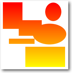
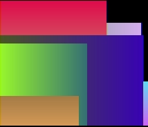
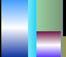
| bottomColor long topColor long yTop long yBottom long yTop = 10 yBottom = 75 drawer.ColorRange(color:red, color:yellow, 200, yTop, yBottom, topColor, bottomColor) drawer.ShadeEllipse(10, yTop, 78, yBottom - yTop, topColor, bottomColor) yTop = 80 yBottom = 180 drawer.ColorRange(color:red, color:yellow, 200, yTop, yBottom, topColor, bottomColor) drawer.ShadeBox(105, yTop, 100, yBottom - yTop, , , topColor, bottomColor) |
| Parameter | Description |
|---|---|
| *longp[,] pt | An array of points. The array is 2 dimensional, with each pair of longs specifying and x and y coordinate pair. |
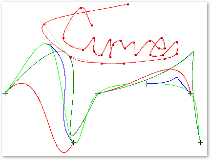
| long ptNum | The number of points to use from the array. If this is set to zero then then it is assumed that all the points in the passed array should be drawn in the curve. |
| Example |
|---|
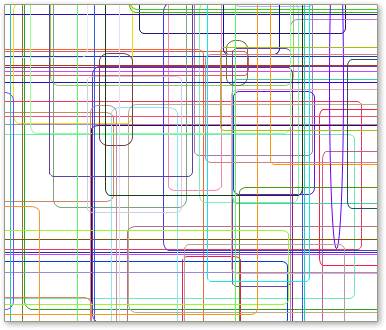
| aCurve
long, dim(1000,2) aCurvePoints long ! number of used entries code aCurve[1,1] = 10 aCurve[1,2] = 200 aCurve[2,1] = 100 aCurve[2,2] = 100 aCurve[3,1] = 150 aCurve[3,2] = 300 aCurve[4,1] = 200 aCurve[4,2] = 200 aCurve[5,1] = 300 aCurve[5,2] = 180 aCurve[6,1] = 390 aCurve[6,2] = 200 aCurve[7,1] = 410 aCurve[7,2] = 300 Drawer.SetPenColor(color:lime) Drawer.Curve(aCurve, 7) Drawer.Display() This example shows code that can be added each time the user clicks on the Draw control, in order to Draw a curve through all of the points clicked. In order to trap mouse clicks place a region control over the Draw control, set the Immediate property of the Region on, and then this code to the Event:Accepted embed. aCurvePoints += 1 if aCurvePoints > 1000 Message('Only 1000 points on the curve supported by this demo, ' | & 'this can be changed by increasing the size of the array.') else aCurve[aCurvePoints, 1] = Drawer.MouseX() aCurve[aCurvePoints, 2] = Drawer.MouseY() end ! draw a dot at each point that the curve will pass through (optional) loop i = 1 to aCurvePoints Drawer.Box(aCurve[i, 1]-1, aCurve[i, 2]-1, 4, 4, color:black) end if aCurvePoints > 1 ! need at least one point to draw a curve if aCurvePoints > 2 ! draw over the previous curve in a pale color to show where it was Drawer.SetPenColor(0DDDDDDh) Drawer.Curve(aCurve, aCurvePoints-1) end Drawer.SetPenColor(color:red) Drawer.Curve(aCurve, aCurvePoints) end
|
| Parameter | Description |
|---|---|
| long x | The x position to start the bounding box at, in pixels |
| long y | The y position to start the bounding box at, in pixels |
| long width | The bounding box width, in pixels |
| long height | The bounding box height, in pixels |
| long lcol | The color of the left hand side of the cylinder - optional |
| long rcol | The color of the right hand side of the cylinder - optional |
| long tcol | The color of the top of the cylinder - optional |
| long bcol | The color of the bottom of the cylinder - optional |
| long xp | The percentage along the x-axis for the highlight - optional |
| long yp | The percentage along the y-axis for the highlight - optional |
| byte intensity | The percentage intensity of the highlight - optional |
| Parameter | Description |
|---|---|
| long depth | this is the depth of the ellipse on the end of the cylinder |
| long eCol | the color of the ellipse on the end of the cylinder |
| Example | |
|---|---|
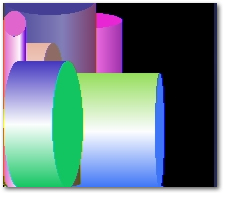
| Drawing a single shaded cylinder with one
color Vertical cylinders, shaded from left to right, the highlight position specified by the XP parameter and the highlight intensity specified by the intensity parameter: drawer.Blank() col = Random(0, 0FFFFFFh) drawer.Cylinder(10, 200, 40, -Random(100, 120), col, col, , | , 60, , 20, Random(50,100), col) drawer.Display() |
 |
| Drawing a single shaded cylinder with two
colors Vertical cylinders, shaded from left to right, the highlight position specified by the XP parameter and the highlight intensity specified by the intensity parameter: drawer.Blank() leftColor = Random(0, 0FFFFFFh) rightColor = Random(0, 0FFFFFFh) drawer.Cylinder(10, 200, 40, -Random(120, 180), leftColor, rightColor, | , , 60, , 20, Random(50,100), leftColor) drawer.Display() |
 |
| Drawing a double shaded cylinder Vertical cylinders, shaded between colors from top to bottom and from light to dark from left to right, with the highlight position specified by the XP parameter and the highlight intensity specified by the intensity parameter. Note that the color is specified as topColor and bottomColor, rather than left and right: drawer.Blank() topColor= Random(0, 0FFFFFFh) bottomColor = Random(0, 0FFFFFFh) drawer.Cylinder(10, 200, 40, -Random(120, 180), , , bottomColor, | topColor, 60, , 20, Random(50,100), topColor) drawer.Display() |
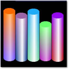 |
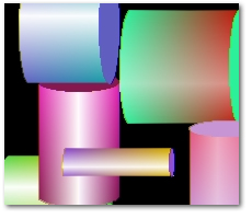
| Drawing a single shaded cylinder -
horizontal Horizontal cylinders, shaded between colors from top to bottom. Identical to the vertical cylinder, but with left and right colors swapped with top and bottom colors, and XP and yp swapped. drawer.Blank() col = Random(0, 0FFFFFFh) drawer.Cylinder(20, 10, Random(100, 120), 40, , , col, col, , | 60, 20, Random(50,100), col) drawer.Display() |
 |
| Drawing a single shaded cylinder with two
colors - horizontal The same as the single color, except top and bottom colors are different. drawer.Blank() topColor = Random(0, 0FFFFFFh) bottomColor = Random(0,0FFFFFFh) drawer.Cylinder(20, 10, Random(100, 120), 40, , , topColor, | bottomColor, , 60, 20, Random(50,100), topColor) drawer.Display() |
 |
| Drawing a double shaded cylinder -
horizontal Horizontal cylinders, shaded between colors from left to right. Identical to the vertical cylinder, but with left and right colors swapped with top and bottom colors, and xp and yp swapped. drawer.Blank() leftColor = Random(0, 0FFFFFFh) rightColor = Random(0, 0FFFFFFh) drawer.Cylinder(20, 10, Random(120, 180), 40, leftColor, | rightColor, , , , 60, 20, Random(50,100), rightColor) drawer.Display() |
 |
| Parameter | Description |
|---|---|
| x, y, width, height | The size of the cylinder bounding box |
| startColor, endColor | The colors to shade from and to. |
| orientation | Whether the cylinder is vertical or horizontal - use either the draw:vertical or draw:horizontal equate. |
| eDepth | The depth of the ellipse on the end of the cylinder |
| eColor, eColor2 | If only eColor is specified, then a solid filled ellipse is drawn, otherwise the ellipse is shaded from eColor to eColor2 |
| angle | The direction that the shading is done in, can either be 0 (from top to bottom) or 90 (from left to right). |
| intensity | How bright the highlight is for Single and Double shading |
| highlightPos | The percentage across the cylinder that the highlight is drawn at. |
| shadingType | One of the following equates: draw:linearShade, draw:singleShade, draw:doubleShade. |
| Example |
|---|
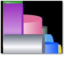
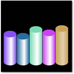
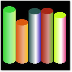
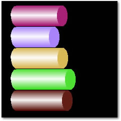
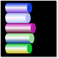
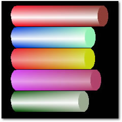
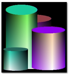
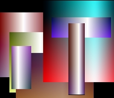
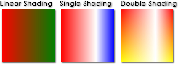
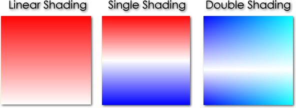
| drawer.Blank(color:white) drawer.SetPenColor(color:none) drawer.Cylinder2(10, 10, 150, 40, color:red, color:yellow, draw:horizontal, 20, | color:red, color:white, 0, 100, 50, draw:singleShade) drawer.SetPenColor(color:red) drawer.Cylinder2(10, 60, 150, 40, color:red, color:yellow, draw:horizontal, 20, | color:red, color:white, 90, 100, 50, draw:doubleShade) drawer.SetPenColor(color:none) drawer.Cylinder2(10, 110, 133, 41, color:aqua, color:navy, draw:horizontal, 20, | color:aqua, color:navy, 0, 100, 50, draw:doubleShade) drawer.Cylinder2(10, 160, 193, 21, color:green, color:lime, draw:horizontal, 10, | color:green, color:lime, 0, 100, 50, draw:doubleShade) drawer.Display() 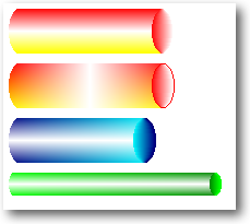 |
| Example |
|---|
| drawer.SetPenColor(color:blue) !
Set the current pen color drawer.Box(1, 20, 100, 120, color:green) ! Draw a box drawer.Display() ! Update the image control |
| Parameter | Description |
|---|---|
| long x | An integer expression that specifies the horizontal position of the starting point. |
| long y | An integer expression that specifies the vertical position of the starting point. |
| long width | An integer expression that specifies the width. |
| long height | An integer expression that specifies the height. |
| long fill | A LONG integer constant, constant EQUATE, or variable containing the red, green, and blue components that create the color in the three low-order bytes (bytes 0, 1, and 2) or an EQUATE for a standard Windows color value. |
| long pQuad | A Long consisting of one or more of the following equates
(added together); quad:TopRight, quad:TopLeft, quad:BottomLeft, quad:BottomRight, quad:Top, quad:Bottom, quad:Left, quad:Right, quad:All. If omitted Quad:All is used. This parameter limits the ellipse to drawing only the quadrants specified. |
| Example |
|---|
| drawer.Blank(color:white) drawer.SetPenColor(color:red) drawer.Ellipse(2, 2, 50, 80) ! draw an ellipse with a red line and no fill drawer.SetPenColor(color:black) ! set the current pen color to black drawer.Ellipse(55, 2, 50, 80, color:blue) ! black line and blue fill drawer.ShadeEllipse(113, 2, 100, 80, color:yellow, color:red ) ! Shade an ellipse from yellow to red drawer.Display() 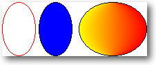 |
| Field | Type | Description |
| name | string(64) | The name of the font, such as 'Arial' or 'Verdana' |
| style | string(32) | The style of the font, 'bold', 'italic' etc. |
| script | string(32) | A string specifying the script, that is, the character set, of the font. For example, Cyrillic. |
| weight | long | Specifies the weight of the font in the range 0 through 1000. For example, 400 is normal and 700 is bold. If this value is zero, a default weight is used. |
| quality | byte | Specifies the output quality. The output quality defines how carefully the graphics device interface (GDI) must attempt to match the logical-font attributes to those of an actual physical font. This specifies whether the font is anti-aliased, non anti-aliased, proof quality, draft quality etc. |
| pitchandfamily | byte | Specifies the pitch and family of the font. The two low-order bits specify the pitch of the font and Bits 4 through 7 of the member specify the font family. |
| Example |
|---|
| drawer.EnumFonts()
! Fill a the drawer.gFontDispQ property with the font
list ! This queue can be use to check a font is installed, displayed in a list or dropdown etc. |
| Parameter | Description |
|---|---|
| long errorCode | The Windows API error code to retrieve the associated error message for. |
| Example |
|---|
| Message('Windows API error ' & GetLastError() & ': ' & drawer.FormatString(GetLastError())) |
| Parameter | Description |
|---|---|
| *string fileData | Pointer to a string that the data from the file will be copied into. The string needs to be large enough to contain the entire contents of the file. If the string is not large enough the method returns the required size and leaves the string untouched. |
| string fileName | A string specifying the path and name of the file to be read into the string |
| Example |
|---|
| dataBuffer &string fName string(File:MaxFileName) fileSize long CODE fileSize = drawer.FileToString(dataBuffer, fName) if fileSize = 0 ! handle the error return 0 end dataBuffer &= New(String(fileSize)) if drawer.FileToString(dataBuffer, fName) = 0 ! handle the error end Dispose(dataBuffer) ! the string must be disposed once it is no longer needed. |
| Property | Description |
| Draw.hScreenRes | The horizontal screen resolution in DPI (dots/pixels per inch) |
| Draw.vScreenRes | The vertical screen resolution in DPI (dots/pixels per inch) |
| Draw.fontResMult | A multiplier that keeps the font size visually the same as the resolution increases. Used internally for the font size calculation. |
| Draw.hScreenSize | The width of the screen in pixels |
| Draw.vScreenSize | The height of the screen in pixels |
| Draw.bitDepth | The current Windows color depth |
| Example |
|---|
| myDrawer.GetDeviceCaps() Message('The current screen dimensions are: ' & myDrawer.hScreenSize & ' x ' & myDrawer.vScreenSize & ' pixels.') |
| Parameter | Description |
|---|---|
| string iconName | The name of the icon to load, if loading from file and the icon is not in the current directory then the path should be specified. |
| ulong hIconModule | A handle to the icon module, as returned by the drwGetModuleHandle() function. The method will get a handle to the current module automatically, this parameter is only provided to allow icons from external modules (DLLs) to be loaded. |
| Example |
|---|
| ! create a
new layer, the same size as the baseLayer: drawer.InitLayer(2, drawer.baseLayer.width, drawer.baselayer.height, 1, 1, color:none) drawer.Withlayer(2) ! make the new layer the current active layer drawer.GetDisplay() ! copy the data in the image control onto the current layer drawer.Display() ! Display all currently visible layers in the image control |
| Example |
|---|
| ! capture
the top left hand corner of the screen and copy it onto the
current draw layer loop x = 1 to drawer.width loop y = 1 to drawer.height drawer.SetPenColor(drawer.GetDevicePixel(x, y)) drawer.PutPixel(x, y) end end drawer.Display() |
| Parameter | Description |
|---|---|
| long x | The x coordinate to place the top left hand corner of the bounding box of the ellipse at. |
| long y | The y coordinate to place the top right hand corner of the bounding box of the ellipse at. |
| long width | Width of the ellipse (the full ellipse, not the half section being drawn) |
| long height | Height of the ellipse (the full ellipse, not the half section being drawn) |
| long innerColor | The color to optionally fill the ellipse section with, if outerColor is specified then the half ellipse is shaded from innerColor to outerColor. |
| long outerColor | If specified then the half ellipse is shaded from innerColor to outerColor. |
| long orientation | The section of the ellipse to draw: 1 = top hemisphere, 2 = bottom hemisphere, 3 = left hemisphere, 4 = right hemisphere. |
hsvColorType 	group, type
h 					real
s 					real
v 					real
				end
Parameters
| Parameter | Description |
|---|---|
| *hsvColorType HSV | An HSVColor group that will be converted to RGB. |
| Example |
|---|
| hsvColorgroup(hsvColorType) end rgbColor long hsvColor.h = 0.333 ! Primary Green hsvColor.s = 1.0 ! Fully saturated hsvColor.v = 0.7 ! Medium green (1.0 would be bright, primary green) rgbColor = Drawer.HsvToRgb(hsvColor) Drawer.SetPenColor(color:black) Drawer.Box(1, 1, 120, 120, rgbColor) Drawer.Display() 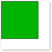 |
| Parameter | Description |
|---|---|
| long x | the x coordinate to place the top left hand corner of the image at. Specifying a negative x value will clip (not draw) the section of the image that falls outside of the layer. |
| long y | the y coordinate to place the top right hand corner of the image at. |
| long width | reserved for future use |
| long height | reserved for future use |
| string fileName | a string specifying the name of the bitmap file to load. |
| long flag | if the value of the flag parameter is draw:tileImage the Image() method will tile the image across the current layer, starting at the coordinates specified by the x and y parameters. |
| long colorMask | colorMask allows a color to be used as an index transparency value, which means that any pixels in the source image that are the same color as colorMask will not be copied onto the destination layer. |
| Example |
|---|
| if drawer.GetImagePixel(1, 1) >
0888888h ! closer to
white than black drawer.Image(drawer.MouseX(), drawer.MouseY(), , , 'fm2_CCCCCCh.bmp', , 0CCCCCCh) else drawer.Image(drawer.MouseX(), drawer.MouseY(), , , 'fm2_333333h.bmp', , 0333333h) end drawer.Display() |
| fm2_333333h.bmp | fm2_CCCCCCh.bmp |
 |
 |
| 1 2 3 4 5 6 7 8 9 10 11 |
imgWidth long imgHeight long curlayer long imglayer long drawer.ImageDimensions(imgWidth, imgHeight, 'myBitmap.bmp') imgLayer = drawer.numlayers + 1 drawer.InitLayer(imglayer, imgWidth, imgHeight, 1, 1, color:none, draw:hidden) curLayer = drawer.activelayer drawer.withlayer(imgLayer) drawer.Image(1, 1, , , 'myBitmap.bmp') |
| 6 7 8 9 10 11 |
get the size of the bitmap file and save the width
and height in imgWidth and imgHeight retrieve the current number of initialized layers and increment it by one create a new layer with the same width and height as the image, create the layer as hidden save the current active layer number select the new layer draw the image from the file onto the new layer |
| Parameter | Description |
|---|---|
| *long width | Variable to receive the width of the image |
| *long height | Variable to receive the height of the image |
| string filename | File name and path of image to retrieve the width and height from |
| Example |
|---|
| iWidth long iHeight long drawer.ImageDimensions(iWidth, iHeight, 'c:\images\foo.bmp') drawer.ImageDimensions(iWidth,iHeight,'myBitmap.bmp') |
| Parameter | Description |
|---|---|
| string dataBuffer | A string containing the RGB data for the image. |
| long x | The x coordinate on the current layer to place the image at. |
| long y | The y coordinate on the current layer to place the image at. |
| long width | The width of the image that is stored in the buffer. |
| long height | The height of the image that is stored in the buffer. |
| long tileX | [Optional] The number of times the images should be tiled (repeated) horizontally. |
| long tileY | [Optional] The number of times the images should be tiled (repeated) vertically. |
| long clipWidth | [Optional] Allows the maximum width to be specified, anything outside of this width will be clipped (removed). This applies to both a single image being placed and when tiling is used. The clipWidth and clipHeight form a bounding box for drawing the image within. |
| long clipHeight | [Optional] The maximum height, allows a bounding box for drawing the image within to be specified. See clipWidth above. |
| Parameter | Description |
|---|---|
| ulong control | Handle to the image control to draw to. |
| Example |
|---|
| Drawer.Init(?Drawer) |
| Example |
|---|
| Drawer.Init256() ! see above for a full example of how to use Init256(), Draw.colours256 and Kill256() |
| Parameter | Description |
|---|---|
| long x | The x coordinate to place the top left hand corner of the image |
| long y | The y coordinate to place the top left hand corner of the image |
| string fileName | The name of the icon to load. If the icon is a resource the name should be an empty string and the hIcon parameter should contain a handle to the icon resource. |
| long width | [Optional] The width of the icon to load |
| long height | [Optional] The height of the icon to load (generally equal to the width) |
| long bpp | [Optional] The color depth of the icon to load (4, 8, 16, 24 or 32 bits per pixel). Not supported in loading icons from resource, the highest bit depth available is used. |
| long index | [Optional] If this is specified all other parameters are ignored at the icon at this position is loaded |
| byte alphaChannel | Not Currently Supported. Specifies the layer alpha channel to copy the icon's alpha channel into. Only valid if the layer the icon is being drawn onto has an alpha channel. Leaving out this parameter will still use the alpha channel of the icon when copying the pixels onto the layer, this just allows you to preserve the transparent area of the icon by copying the alpha values of the icon pixels into the alpha channel. |
| ulong hIcon | When loading from an icon resource the hIcon parameter should contain a handle to the icon resource. |
| Example |
|---|
| Load and icon using variables for the required size (reqWidth)
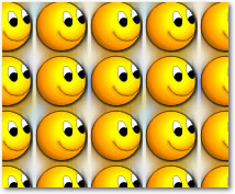
and color depth (reqColors): if Drawer.LoadIcon(xpos, ypos, 'myIcon.ico', reqWidth, , reqColors) ! icon loaded else ! handle errors here, ErrorTrap() will display ! information if Drawer.suppressErrors = 0 end Load a 48x48 icon with 32 bit color, within an icon file containing many icons: Drawer.LoadIcon(10, 10, 'smile.ico', 48, 48, 32) Load the first icon in the file, or there is only one icon: Drawer.LoadIcon(10, 10, 'smile.ico') If you know the position of the icon you would like to load in the icon file: ! load the image that is at position 3 in the icon file Drawer.LoadIcon(10, 10, 'smile.ico', , , , 3 Load an icon, either from a resource or a file, specify the size and color depth, but if they don't exist then load whichever icon exists: if Instring('~', IconName, 1, 1) ! Icon is a resource, not from disk hIcon = ds_GetHIcon(IconName, , 32) ! Attempt to fetch the 32x32 icon if hIcon = 0 ! If no 32x32 then fetch the first icon in the resource hIcon = ds_GetHIcon(IconName) end if hIcon = 0 ! Report error: Could not load the icon. The icon resource could not be located. else Drawer.Loadicon(1, 1, '', 32, 32, 32, , , hIcon) ! Load the icon from a resource end else ! Load the icon from disk if not Drawer.Loadicon(1, 1, IconName, 32, 32, 32) ! Try load the 32 bit icon (32x32 pixels) if not Drawer.Loadicon(1, 1, IconName, 32, 32) ! Any bit depth (32x32 pixels) Drawer.Loadicon(1, 1, IconName) ! Any icon end end end |
| Parameter | Description |
|---|---|
| string messageStr | A string to print to the debug output. There is no Draw limit on the length of the string. |
| Example |
|---|
| Drawer.logging = 1 !
enable logging Drawer.suppressErrors = 1 ! hide any error messages from the end user (only send errors to the debug output) Drawer.Log('Draw box at: ' & xpos & ', ' & ypos) Drawer.Log('Current layer width: ' & Drawer.width & ', current layer height: ' & Drawer.height) |
| Parameter | Description |
|---|---|
| long x | The x coordinate of the top left hand corner of the bounding box of the ellipse |
| long y | The y coordinate of the top left hand corner of the bounding box of the ellipse |
| long width | Width of the ellipse |
| long height | Height of the ellipse |
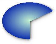
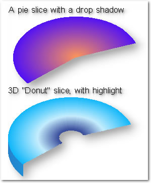
| long pSlice | The data structure that defines how the pie slice will be drawn (see below) |
| PieSlice Group Type | |||
|---|---|---|---|
| Name | Type | Default | Description |
| startAngle | long | 0 | The angle that the slice starts at, in tenths of degrees (10 = 1 degree) measured counter-clockwise from three o'clock. |
| endAngle | long | 0 | The angle that the slice ends at, in tenths of degrees (10 = 1 degree) measured counter-clockwise from three o'clock. |
| outerColor | long | color:none | The color at the outer edge of the pie slice |
| innerColor | long | color:none | The color at the inner edge of the pie slice |
| borderColor | long | color:none | An optional parameter that specifies the color of a line around the pie slice (by default no border is drawn) |
| highlightPos | long | 0 | Specifies that a highlight should be be created (the shading shades from outerColor to the highlight and then to innerColor). This value is the percentage across the slice that the highlight should be drawn at. |
| highlightIntensity | long | 0 | The intensity of the highlight, from 0 to 100 (where zero is no highlight and 100 is pure white). |
| startRadius | long | 0 | The radius to start the slice at (allows the slice to be smaller than the full ellipse). Percentage value from 0 to 100. |
| endRadius | long | 100 | The radius to end the start at (this creates a "donut" slice, where the slice ends before the center of the ellipse). Percentage from 0 to 100. |
| dropHeight | long | 0 | Optional parameter to specify the 3D drop section of the pie slice. Note in version 2.10 only the curved section of the drop is drawn, future versions will also draw the polygonal "edges" of the pie slice. |
| dropType | long | 0 | Specifies the type of shading to use for the 3D drop section of the pie slice. This can be set to Draw:Horizontal, Draw:Vertical or Draw:Solid, which do horizontal, vertical or no shading respectively. |
| dropColor1 | long | color:none | The color to use for the drop section of the slice. If dropType is not set to Draw:Solid then this is the color to start shading from. |
| dropColor2 | long | color:none | The color to shade the drop to. |
| dropHighlightPos | long | 0 | Specifies a highlight position in the shading for the drop section of the slice, values range from 0 to 100. |
| dropHighlightIntensity | long | 0 | The intensity of the highlight, from zero (which does not draw any highlight at all) to 100 (pure white). |
| Example |
|---|
| sAng long(200) eAng long(2200) width long(250) height long(160) CODE drawer.Blank(color:white) curSlice.startAngle = sAng curSlice.endAngle = eAng ! ------------- The first pie slice ----------- ! curSlice.outerColor = Random(color:white, color:black) curSlice.innerColor = Random(color:white, color:black) curSlice.startRadius = 0 curSlice.endRadius = 100 curSlice.dropHeight = 0 curSlice.highlightPos = 0 curSlice.highlightIntensity = 0 drawer.PieSlice(30, 40 , width, height, curSlice) ! ----------- The Second Pie Slice ------------ ! curSlice.outerColor = Random(color:white, color:black) curSlice.innerColor = Random(color:white, color:black) curSlice.highlightPos = Random(30, 70) curSlice.highlightIntensity = Random(40, 80) curSlice.startRadius = 20 curSlice.endRadius = 100 curSlice.dropHeight = 25 curSlice.dropColor1 = curSlice.outerColor curslice.dropColor2 = curSlice.innerColor drawer.PieSlice(20, 200 , width, height, curSlice) drawer.Display() |
| Parameter | Description |
|---|---|
| *long[] vertices | An array that defines the vertices for the polygon. Each pair of entries in the array define the x and y coordinates of a vertex. For example to draw a quadrilateral you would need an array with 8 entries to specify the four vertices. |
| long fill=-1 | The fill color to be used for the polygon. The default value is no fill (color:none), which draws a line only polygon. |
| long numVertices=0 | Allows the number of vertices to be specified if there are more entries in the the array than there are vertices required. For example the first 8 entries in an array of 256 elements could be set to the coordinates for the four vertices of a quadrilateral, this parameter would then be set to 4 to ensure that only the first 4 vertices (8 array entries) are used. If this number is set to great than half the size of the array, then there are not sufficient entries in the array for the number of vertices required and the function will return and call ErrorTrap with the error description. |
| Example |
|---|
drawer.Blank(color:white) ! Clear the Draw control !---- Create the quad ----! pVertices[1] = Random(5, 60) pVertices[2] = Random(105, 160) pVertices[3] = Random(120, 200) pVertices[4] = Random(105, 160) pVertices[5] = Random(120, 200) pVertices[6] = Random(220, 300) pVertices[7] = Random(5, 60) pVertices[8] = Random(220,300) drawer.SetPenColor(color:none) ! Draw the polygon without a line around it drawer.Polygon(pVertices, color:red) ! Draw a polygon with a red fill drawer.Display() |
| Parameter | Description |
|---|---|
| *long[] vertices | An array that defines the vertices for the polygon. Each pair of entries in the array define the x and y coordinates of a vertex. For example to draw a quadrilateral you would need an array with 8 entries to specify the four vertices. |
| long numVertices | Allows the number of vertices to be specified if there are more entries in the the array than there are vertices required. For example the first 8 entries in an array of 256 elements could be set to the coordinates for the four vertices of a quadrilateral, this parameter would then be set to 4 to ensure that only the first 4 vertices (8 array entries) are used. If this number is set to great than half the size of the array, then there are not sufficient entries in the array for the number of vertices required and the function will return and call ErrorTrap with the error description. |
| long x | The x-coordinate of the point to check. |
| long y | The y-coordinate of the pint to check. |
| Example |
|---|
| !---- Create the quad ----! pVertices[1] = Random(5, 60) pVertices[2] = Random(105, 160) pVertices[3] = Random(120, 200) pVertices[4] = Random(105, 160) pVertices[5] = Random(120, 200) pVertices[6] = Random(220, 300) pVertices[7] = Random(5, 60) pVertices[8] = Random(220,300) if drawer.PointInPolygon(pVertices, 4, drawer.MouseX(), drawer.MouseY()) Message('The mouse is currently in the polygon') end |
| Parameter | Description |
|---|---|
| width | [Optional] The width to resize to. If not specified, or less than 1, the width is set to the current width of the Image control |
| height | [Optional] The height to resize to. If not specified, or less than 1, the height is set to the current height of the Image control |
| copyData | [Optional]. If this is passed as non zero then the image data is copied into the new buffer, otherwise the image is cleared to black. |
| Example |
|---|
!--- Resize the buffer to the current image control size
Drawer.Resize()
!--- Resize the buffer to 180 by 400 pixels, note that the control size is not changed
Drawer.Resize(180, 400)
!--- Resize all layers Drawer.Resize() ! Resize the base layer loop i = 2 to DRAW:NUMLAYERS ! Resize any other layers that have been initialized if Drawer.layers[i].init ! Layer is in use Drawer.ResizeLayer(i, Drawer.baseLayer.width, Drawer.baseLayer.height) end end |
hsvColorType 	group, type
h 					real
s 					real
v 					real
				end
Parameter
| Parameter | Description |
|---|---|
| long rgbColor | A standard clarion RGB color, such as 0FF66FFh, color:red etc. |
| *hsvColorType HSV | An HSVColor group that the converted color will be placed into. |
| Example |
|---|
| hsvColor
group(hsvColorType) end Drawer.RgbToHsv(color:red, hsvColor) |
| Parameter | Description |
|---|---|
| long x | The x (horizontal) position to place the object at. |
| long y | The x (vertical) position to place the object at. |
| long width | The width (in pixels) of the rectangle. |
| long height | The height (in pixels) of the rectangle. |
| long eWidth | The width of the bounding box that would encompass the ellipse that the round corner is formed from. For a corner that is 10 pixels wide, this should be set to 20 pixels. |
| long eHeight | The height of the bounding box that would encompass the ellipse that the round corner is formed from. For a corner that is 10 pixels high, this should be set to 20 pixels. |
| long lineColor | The color of the rectangle's line. If this is omitted, then the current pen color is used. |
| long fill | The color to fill the rectangle. If this is omitted then the rectangle is not filled. |
| Parameter | Description |
|---|---|
| ulong Color | The color to set the pen to, range from 0 (black) to 0FFFFFFh (white). Hex colors are stored as BGR. |
| Example |
|---|
| Drawer.SetPenColor(color:red)
! set pen color to red Drawer.SetPenColor(0FFFF00h) ! set pen color to yellow Drawer.SetPenColor(65280) ! set pen color to green |
| Parameter | Description |
|---|---|
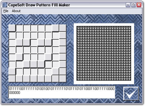
| String pattern | A string of ones and zeros which represent and 8 x 8 pixel pattern. |
| Example |
|---|
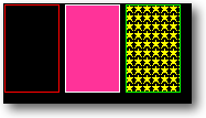
| drawer.SetFill(pattern:stars)
! set the fill pattern to a Draw
pattern equate drawer.SetPenColor(color:red) ! set pen color to red drawer.Box(10, 10, 120, 120, color:red) ! draw a red box with a patterned fill |
| Parameter | Description |
|---|---|
| String pName | the name of the typeface to use. Like Arial, or Tahoma etc. If omitted or blank it defaults to the font of the current window. |
| Long pSize | The size of the font to use. If omitted it defaults to the font size of the current window. |
| Long pColor | The color of the font to use. If you are only changing the color then use the SetFontColor method instead. If omitted the color of the font of the current window is used. |
| Long pStyle | The style of the font. Equates like Font:Regular, Font:Bold and Font:Italic can be used. If omitted the style of the window font is used. |
| Long pCharset | The Charset of the font to use. If omitted the charset of the window is used. |
| Parameter | Description |
|---|---|
| ulong color | The color to set the font to, range from 0 (black) to 0FFFFFFh
(white). Hex colors are stored as BGR. |
| Parameter | Description |
|---|---|
| ulong mode | The text rending mode. It can be one of the following values: These three modes use the current user anti-aliasing settings (the windows font smoothing settings): Draw:DEFAULT_QUALITY Draw:DRAFT_QUALITY Draw:PROOF_QUALITY To draw non anti-aliased text set mode to: Draw:NONANTIALIASED_QUALITY To draw anti-aliased text set the mode to: Draw:ANTIALIASED_QUALITY Not that smooth (anti-aliased) font are supported in Windows 95 Plus! and later. |
| Example |
|---|
| Drawer.SetFontMode(Draw:NONANTIALIASED_QUALITY) ! turn off font smoothing Drawer.SetFontMode(Draw:ANTIALIASED_QUALITY) ! turn on font smoothing Drawer.SetFontMode(Draw:DEFAULT_QUALITY) ! use the current Windows font smoothing setting |
| Parameter | Description |
|---|---|
| long x | The x position to start the box at, in pixels |
| long y | The y position to start the box at, in pixels |
| long width | The box width, in pixels |
| long height | The box height, in pixels |
| long lcol | The color of the left hand side of the box - optional |
| long rcol | The color of the right hand side of the box - optional |
| long tcol | The color of the top of the box - optional |
| long bcol | The color of the bottom of the box - optional |
| long XP | The percentage along the x-axis for the highlight - optional |
| long yp | The percentage along the y-axis for the highlight - optional |
| byte intensity | The percentage intensity of the highlight - optional |
| Parameter | Description |
|---|---|
| long x | x coordinate of the top left hand corner of the ellipse's bounding box |
| long y | y coordinate of the top left hand corner of the ellipse's bounding box |
| long width | The height of the ellipse, in pixels |
| long height | The width of the ellipse, in pixels |
| long startColor | The color to start shading from |
| long endColor | The color to shade to |
| long direction | The shading direction. Currently Draw:Horizontal (the default) and Draw:Vertical are supported. |
| Example |
|---|
| drawer.Blank() drawer.SetPenColor(color:red) drawer.ShadeEllipse(10, 10, 180, 100, color:red, color:green) drawer.Display() 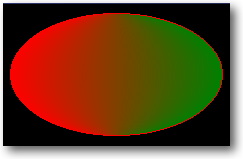 |
| Parameter | Description |
|---|---|
| long startColor | The color to start shading from |
| long endClor | The color to end shading at |
| Parameter | Description |
|---|---|
| *long[] vertices | An array that defines the vertices for the polygon. Each pair of entries in the array define the x and y coordinates of a vertex. For example to draw a quadrilateral you would need an array with 8 entries to specify the four vertices. |
| long startColor=-1 | The fill color to be used for the polygon. The default value is no fill (color:none), which draws a line only polygon. If endColor is specified the the polygon is shaded from startColor to endColor. Currently only linear horizontal shading is supported. |
| long endColor=-1 | Specifies the color to shade to. The parameter is optional, if not color is specified then the polygon is either dran with a solid fill (if startColor is specified) or with no fill (if both startColor and endColor are not specified). |
| long numVertices=0 | Allows the number of vertices to be specified if there are more entries in the the array than there are vertices required. For example the first 8 entries in an array of 256 elements could be set to the coordinates for the four vertices of a quadrilateral, this parameter would then be set to 4 to ensure that only the first 4 vertices (8 array entries) are used. If this number is set to great than half the size of the array, then there are not sufficient entries in the array for the number of vertices required and the function will return and call ErrorTrap with the error description. |
| Example |
|---|
 ! DATA
pVertices   long, dim(8)

! CODE
drawer.Blank(color:white)                ! Clear the Draw control
!---- Create the quad ----! pVertices[1] = Random(5, 60) pVertices[2] = Random(105, 160) pVertices[3] = Random(120, 200) pVertices[4] = Random(105, 160) pVertices[5] = Random(120, 200) pVertices[6] = Random(220, 300) pVertices[7] = Random(5, 60) pVertices[8] = Random(220,300)drawer.SetPenColor(color:none) ! Draw the polygon without a line around it drawer.ShadePolygon(pVertices, color:red, color:green) drawer.Display() 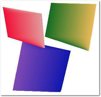 |
| Example |
|---|
| drawer.Blank(color:white) drawer.fontName = 'Arial' drawer.fontStyle = font:bold + font:italic drawer.fontSize = 12 drawer.SetFontColor(color:red) drawer.Show(10, 10, 'CapeSoft Draw TrueType Text') drawer.Display() |
Draw:ANSI_CHARSETDraw supports complex script languages such as Arabic and Japanese, where multiple character can combine and form single character and space can be modifed depending on content etc. Draw automatically calls Draw.ShowFull() for complex script languages based on the value of the Draw.FontCharSet property (all those marked above as Complex Script languages). You can also force this behaviour by setting Draw.renderWholeStrings = 1.
Draw:DEFAULT_CHARSET
Draw:SYMBOL_CHARSET
Draw:SHIFTJIS_CHARSET (Complex Script)
Draw:HANGEUL_CHARSET (Complex Script)
Draw:HANGUL_CHARSET (Complex Script)
Draw:GB2312_CHARSET (Complex Script)
Draw:CHINESEBIG5_CHARSET (Complex Script)
Draw:OEM_CHARSET
Draw:JOHAB_CHARSET (Complex Script)
Draw:HEBREW_CHARSET (Complex Script)
Draw:ARABIC_CHARSET (Complex Script)
Draw:GREEK_CHARSET
Draw:TURKISH_CHARSET
Draw:VIETNAMESE_CHARSET (Complex Script)
Draw:THAI_CHARSET (Complex Script)
Draw:EASTEUROPE_CHARSET
Draw:RUSSIAN_CHARSET
Draw:MAC_CHARSET
Draw:BALTIC_CHARSET
| Parameter | Description |
|---|---|
| string textString | The string that you want the height calculated for (optional, see note above). |
| Parameter | Description |
|---|---|
| string text | The string that you want the width calculated for. |
| Parameter | Description |
|---|---|
| long x | x coordinate of the top left hand corner of the ellipse's bounding box |
| long y | y coordinate of the top left hand corner of the ellipse's bounding box |
| long width | The height of the ellipse, in pixels |
| long height | The width of the ellipse, in pixels |
| long outerColor | The color at the outer edge of the ellipse |
| long endColor | the color at the highlight point |
| real yOffset | The vertical offset from center to draw the highlight at. 0 is the top, 0.5 is the center and 1.0 is the bottom. |
| real xOffset | the horizontal offset from the center to draw the highlight at. 0 is the far left, 0.5 is the center and 1.0 is the far right. |
| Example |
|---|
| drawer.Blank(color:white) drawer.SetPenColor(color:none) drawer.Sphere(10, 10, 120, 200, color:red, color:white, 0.5, 1) drawer.Sphere(130, 10, 120, 120, color:red, color:yellow, 0, 0) drawer.Display() 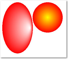 |
| Parameter | Description |
|---|---|
| long x | x coordinate of the start point of the line |
| long y | y coordinate of the start point of the line |
| long angle | The angle to draw the line at, in degrees, with zero at 3 O'Clock |
| long length | The length of the line, in pixels |
| long startPos | Reserved for future use |
| long endPos | Reserved for future use |
| long startColor | The color at the start of the line at if a shaded line is being drawn |
| long endColor | The color at the end of the line if a shaded line is being drawn. |
| Example |
|---|
curAngle			long

CODE

	drawer.Blank(color:white)
	drawer.SetPenColor(color:red)
	drawer.SetPenWidth(1)
loop curAngle = 0 to 360 by 10
   	drawer.radLine(150,150, curAngle, 120, , , color:red, color:yellow)
end
drawer.Display()
 |
| Parameter | Description |
|---|---|
| x | The x coordinate of the rectangular region that display is limited to. |
| y | The y coordinate of the rectangular region that display is limited to. |
| w | The width of the rectangular region that display is limited to. |
| h | The height of the rectangular region that display is limited to. |
| Example |
|---|
binaryString			string(4096)
textString				string(1024)

  CODE
! assume that binaryString has been filled with 4K of binary data... ! write to a file, always create a new file, and write the entire string to disk with no clipping drawer.StringToFile(binaryString, 'myData.bin', 1, 0) textString = '<<html><13,10><<head><13,10>' | & '<<title>Test HTML Page<</title><13,10>' | & '<</head><13,10><<body><13,10>' | & '<<h1>This is an HTML page<</h1><13,10>' | & '<</body><13,10><</html>' ! write some plain text to an html file, always create a new file, and write the clipped data to disk (no trailing spaces) drawer.StringToFile(textString, 'test.html', 1, 1) |
| Example |
|---|
|
Drawer.WriteBMP('c:\my documents\my
pictures\test.bmp') ! Or you can pass just the filename, and the path is assumed to be the current directory: Drawer.WriteBMP('test.bmp') |
| Example |
|---|
|
drawer.WithLayer(2) ! select the
second layer drawer.WriteLayerBMP('c:\my documents\my pictures\layer2.bmp') ! Or you can pass just the filename, and current directory will be used as the path (See SetPath() in the Clarion docs) drawer.WritelayerBMP('layer2.bmp') |
| Example |
|---|
|
drawer.WithLayer(2) ! select the second layer drawer.WriteLayerPNG('c:\my documents\my pictures\layer2.png'/span) ! Or you can pass just the filename, and the path is assumed to be the current directory: drawer.WriteLayerPNG('layer2.png'/span) |
| Example |
|---|
|
p1 like(Point3D) p1.x = 1.25 p1.y = 2.117 p1.z = 0 ! Use a zero z coord for 2D |
| Example |
|---|
|
line1 like(Line3D) line1.p0.x = 1.5 ! a line3D is defined as two points: P0 and P1, each of which have and x, y and z coordinate line1.p0.y = 2.5 line1.p0.z = 0 line1.p1.x = 5.0 line1.p1.y = 12.25 line1.p1.z = 0 |
| Draw.Add3D | Add two points or vectors |
| Draw.CrossProd | Calculate the cross product of two vectors (or points) |
| Draw.Dot | Calculate the dot product of two vectors |
| Draw.Distance | Calculate the distance from a line to a point |
| Draw.Equal3D | Determine equality of two vectors or points |
| Draw.LinesIntersect | Determine if two lines intersect, and if so the point of intersection |
| Draw.Perp | Calculate the length of the perpendicular |
| Draw.PointOnLine | Determine if a point is on a line, and if so where. |
| Draw.ScalarProd | Calculate the scalar product of a point or vector multiplied by a real number |
| Draw.Sub3D | Subtract two points or vectors |
| Example |
|---|
| v1
like(vector) v2 like(vector) v3 like(vector) Drawer.Add3D(v1, v2, v3) ! v3 = v1 + v2 |
 The
dot product of X and Y is show in red.
The
dot product of X and Y is show in red.
| Example |
|---|
| line1 like(line3D) point1 like(point) dist long line1.p0.x = 1.5 ! a line3D is defined as two point: P0 and P1, each of which have and x, y and z coordinate line1.p0.y = 2.5 line1.p0.z = 0 line1.p1.x = 5.0 line1.p1.y = 12.25 line1.p1.z = 0 point1.x = 0 ! check the distance from the origin to the line we have specified point1.y = 0 point1.z = 0 dist = Distance(point1, line1) |
| antiAlias | Enables or disabled anti-aliased drawing of basic primitives. Set to True
(1) to enable anti-aliasing, and False (0) to disable it. When objects are drawn on the screen they are drawn using pixels, which are square. This means that objects drawn are approximations, and can result in "jagged" or "stepped" edges. Anti-aliasing provides smoothing by blending the edge pixels slightly with the background that the object is being drawn onto. The image below demonstrates the effects of anti-aliasing on objects and text (the right hand side is anti-aliased, the left is not). 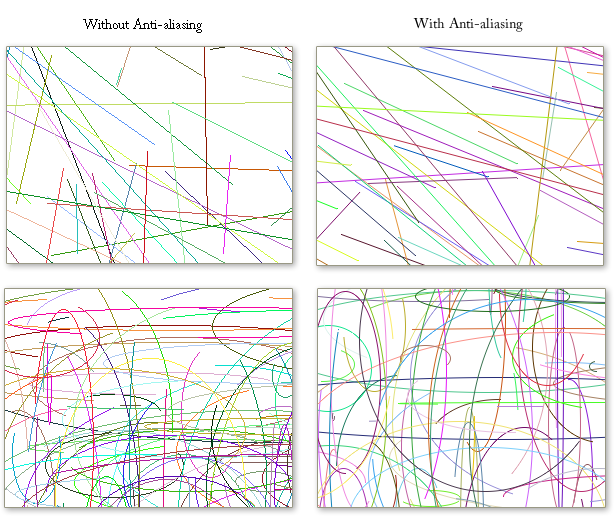 Note that anti-aliasing will improve the visual quality, however there is a speed impact, as it takes significantly more processing to render anti-aliased objects. | |
| bitmapFileData | &string | A handle to the Bitmap buffer of the current layer. You can change the buffer directly to implement per pixel, or even per channel effects. The buffer is stored as a Bitmap, with three bytes per pixel (BGR), a 54 byte header and each scanline is zero padded so that it ends on a word boundary. |
| colors256 | long | Flag to enable or disable 256 colour drawing once Init256() has been called. See the Init256() documentation for drawing in 256 colours and how to use the colors256 flag. |
| fontColor | long |
We advise that you do not set this property directly, call the .SetFontColor()
method. The font color. You can set the font color by calling SetFontColor(). If you do set this manually make sure you set the .fontred, .fontgreen, .fontblue properties. See the SetFontColor or SetPenColor methods for how to get the relevant bytes. Draw.fontRed byte Draw.fontGreen byte Draw.fontBlue byte TThe individual font colour components |
| fontName | A string for the name of the font drawn by the Show()
method. Examples drawer.fontName = 'Arial' drawer.fontName = 'Times New Roman' See the Show() method for more details. | |
| fontCharset | The character set used for rendering the fonts. The Draw.FontCharSet
property can be set to any of the following values as required in order to
change the: Draw:ANSI_CHARSET Draw:DEFAULT_CHARSET Draw:SYMBOL_CHARSET Draw:SHIFTJIS_CHARSET (Complex Script) Draw:HANGEUL_CHARSET (Complex Script) Draw:HANGUL_CHARSET (Complex Script) Draw:GB2312_CHARSET (Complex Script) Draw:CHINESEBIG5_CHARSET (Complex Script) Draw:OEM_CHARSET Draw:JOHAB_CHARSET (Complex Script) Draw:HEBREW_CHARSET (Complex Script) Draw:ARABIC_CHARSET (Complex Script) Draw:GREEK_CHARSET Draw:TURKISH_CHARSET Draw:VIETNAMESE_CHARSET (Complex Script) Draw:THAI_CHARSET (Complex Script) Draw:EASTEUROPE_CHARSET Draw:RUSSIAN_CHARSET Draw:MAC_CHARSET Draw:BALTIC_CHARSET See Also StrLen(), Show(), fontSize, fontName, SetFontColor(), fontCharset, fontStyle, SetFontMode(), SetFontColor() | |
| fontStyle | A combination of the font weight and style equates. Example Drawer.fontStyle = FONT:Bold + FONT:Italic + FONT:Underline. See the a href="#Show">Show() method for more details. See Also StrLen(), Show(), fontSize, fontName, SetFontColor(), fontCharset, fontStyle, SetFontMode(), SetFontColor() | |
|
fontSize | The point size of the font used by the Show()
method. Example drawer.fontSize = 12 ! draw 12 point text/span> See Also StrLen(), Show(), fontSize, fontName, SetFontColor(), fontCharset, fontStyle, SetFontMode(), SetFontColor() | |
| fontZoom | Setting the fontZoom factor allows you to adjust for increased resolution. This is particularly useful on reports with high resolution Draw controls. See the section on Drawing on Reports for more details on using the fontZoom property. The default value for fontZoom is 1, increasing fontZoom will increase the size that fonts are drawn at any particular point size. This allows you to use a 12 point font on a high resolution report, simply by increasing the fontZoom factor to adjust for the resolution. | |
| height | long | The height of the current layer, in pixels. The height of the actual Draw image is Draw.baseLayer.height. |
| penColor | long | Setting this property directly is not
recommended, use the .SetPenColor() method. The pen color. You can set the pen color by calling the SetPenColor() method. If you set this manually make sure you set penred, pengreen and penblue properties. See the SetPenColor() method for how to get the relevant bytes. penRed string(1) penGreen string(1) penBlue string(1) Individual pen colour components. |
| penStyle | long | The pen style, uses the same equates as Clarion pen styles. |
| penWidth | long | The pen width in pixels. |
| suppressErrors | byte(1) | Whether the ErrorTrap() method displays a
message, default suppressErrors is 1, and no messages are displayed. Example Drawer.suppressErrors = 1 ! suppress all error messages Drawer.suppressErrors = 0 ! display all error messages |
| textAlignRTL | Sets the text to display in Right-To-Left reading order for languages such
as Hebrew. See the Show() method. Example drawer.textAlignRTL = true ! Use RTL text order. See Also StrLen(), Show(), fontSize, fontName, SetFontColor(), fontCharset, fontStyle, SetFontMode(), SetFontColor() | |
| width | long | The width of the current layer in pixels. The width of the Draw image is Draw.baseLayer.width. |